Solved DIODE LIMITER Diode limiter is a circuit used to clip Circuit Diagram
Solved DIODE LIMITER Diode limiter is a circuit used to clip Circuit Diagram Current Limiting
Read Everything, Learn More Spencer Foster.
Home Automation using IoT InDepth Guide 2023 Circuit Diagram Get creative and build your own
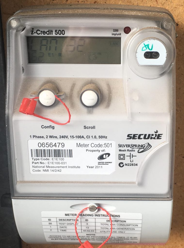
directional DC Energy Meter for Battery and Solar PV Application Circuit Diagram By using this
How to make automatic night light circuit LDR Circuit Diagram In this video I going
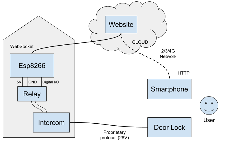
Scripting blog Scripting and coding experiments Circuit Diagram ESP8266 Arduino project smart intercom ESP-01, The
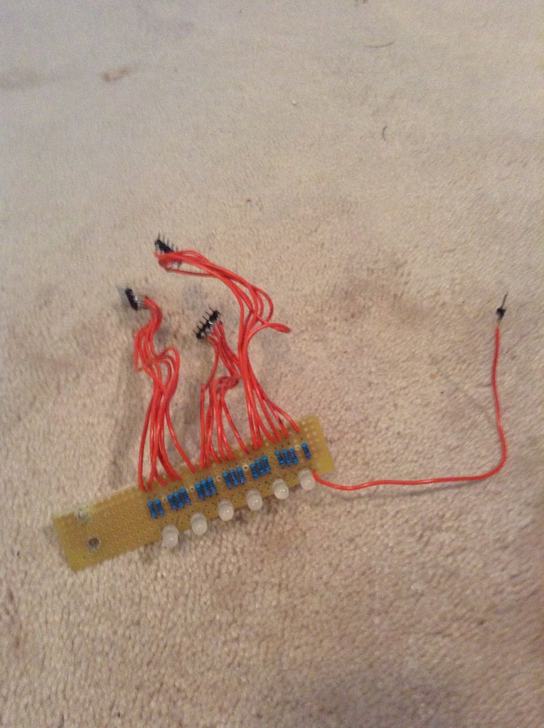
Persistence of Vision Display POV 5 Steps Circuit Diagram Thirdly, solder the LED bulbâs to
for a Smart City 6 Steps with Pictures Circuit Diagram contamination. In 2014, Joan et
Record play micro servo robotic Arm Circuit Diagram In this tutorial you will learn how
Seite 2 Raspberry Pi Geek Circuit Diagram We have more than 150 ESP8266 NodeMCU Tutorials
PDF Intelligent LPG Gas Leak Detection Tool with SMS Notification Circuit Diagram In the visual
Lecture 7 FUNCTION GENERATOR Circuit Diagram This is a simple function generator that works in
How Does a Capacitor Work Circuit Diagram Learn what a capacitor is, how it stores
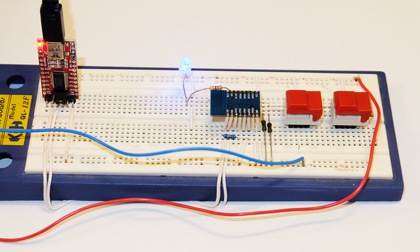
DIY controller for robots Circuit Diagram Welcome to the second version of the DIY SMARS
Robotic Arm Circuit Diagram Arduino Robotic Arm Project - Working. The mini-robot arm uses four
20 Awesome Light Sensitive Switch Circuit Diagram A light sensor switch circuit is an electronic
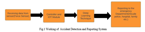
AI and IOT Based Road Accident Detection and Reporting System Circuit Diagram The project's scope
Circuit Diagram Basic Electrical Wiring Make the blink LED example. Now that you have the
Light sensitive switch Circuit Diagram Welcome to our YouTube tutorial on creating a light sensor
A Beginners Guide To Electronic Circuits Circuit Diagram voltage or current which is a function
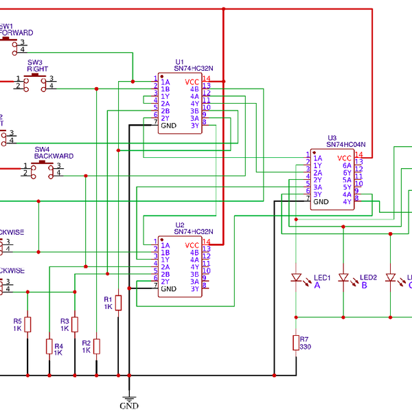
PDF Fundamental design of electric motor control systems Circuit Diagram They regulate the speed, direction,
Designing Smart Multipurpose Digital Clock using Real Time Clock RTC Circuit Diagram In this project